ANESTHESIA MACHINE

GLOSARY

Vaporizer: Anesthetic agent delivery system OR Vapor delivery system A ‘vaporizer’ is a device that changes a liquid anesthetic agent into its vapor and adds a controlled amount of that vapor to the fresh gas flow or the breathing system.

Anesthesia: Loss of feeling or awareness, as when an anesthetic is administered before surgery.

Canister: A box or container; in anesthesiology, the container for carbon dioxide absorbent.

Canister: A box or container; in anesthesiology, the container for carbon dioxide absorbent.
Soda Lime: A mixture of sodium and calcium hydroxides used to absorb exhaled carbon dioxide in an anesthesia rebreathing system. Soda-lime glass beads are used in air-fluidized beds.
INTRODUCTION
The most important equipment used by the anesthesiologist is the anesthesia machine. The basic function of an anesthesia machine is to prepare a mixture of gases of known composition but variable with precision. The gas mixture can be delivered to a breathing system. The anesthesia machine itself has evolved from a simple pneumatic device to a complex set of mechanical, electrical and computer-controlled components. Therefore, knowledge of the basic design of the anesthesia machine is essential for all practicing anesthesiologists to understand the modern anesthesia station.
The purpose of a vaporiser is to add anaesthetic vapor into the fresh gas flow in a way that the output of the vaporiser delivers the set concentration of anaesthetic agent accurately.


* One way or unidirectional valves: are paired valves which direct gas flow away from the patient on expiration and toward the patient on inspiration, preventing the rebreathing of exhaled gases before they pass through Understanding the anesthesia machine the absorbent canister. Upon inspiration, the gas mixture is delivered through the inspiratory valve into the breathing tube and Y-piece, then to the patient. At this time the reservoir bag will deflate. When the patient exhales, the expired gases enter the Y-piece and flow through the breathing tube and expiratory valve. Circuit components are arranged to allow movement of the gas mixture in one direction.
The pop-off valve, also called an adjustable pressure-limiting valve, relief valve, or overflow valve vents gas to the scavenger system to prevent the build up of excessive pressure within the circle

Gaseous of the anesthesia machine :
*Nitrous Oxide:
*Parts of the machine :


THEORETICAL FRAMEWORK
FUCTION VAPORISER:
The purpose of a vaporiser is to add anaesthetic vapor into the fresh gas flow in a way that the output of the vaporiser delivers the set concentration of anaesthetic agent accurately.
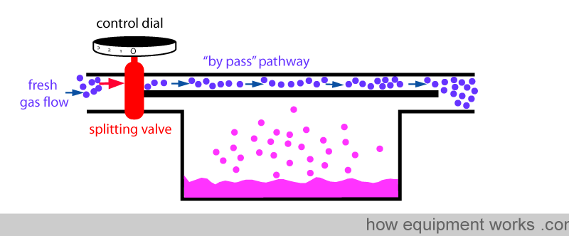
Fresh gas enters the inlet of the vaporiser and is divided into two flow pathways. The splitting valve, depending on the setting of the control dial, adjusts how much goes through each of the pathways. The fresh gas that is sent along the “by pass” pathway doesn’t come into contact with any vapor. On the other hand, the fresh gas that is sent to the vaporising chamber becomes fully saturated with vapor. At the exit end of the vaporiser, the by pass gas (vaporless) meets the chamber gas (fully saturated with vapor) and the two mix. The resultant output depends on how much of fresh gas went though each of the pathways.

When you dial a high anaesthetic concentration requirement, the splitting valve sends more fresh gas via the vaporising chamber.Similarly, when you dial a low anaesthetic concentration requirement, the splitting valve sends less fresh gas via the vaporising chamber.Finally, when you set the dial to zero to make vaporiser deliver no anaesthetic vapor, the splitting valve sends all the fresh gas via the by pass pathway and nothing through the vaporising chamber.

Valves of the machine:
* O2 flush valve : bypasses the vaporizer and delivers oxygen gas only to the common gas outlet and then to the breathing circuit. Used to fill the breathing circuit with oxygen, it delivers a high but unmetered flow of oxygen. This flow, approximately 30 to 50 L/min, can quickly fill the breathing system.
* Pop-off valve:The gas mixture enters the breathing system through the fresh gas inlet - the location at which gases from the common gas outlet of the anesthesia machine (or from
the outlet of the vaporizer) enter the circle system. The inlet is usually located on the inspiratory side of a rebreathing system. This location minimizes the dilution of the fresh gas with expired gases, absorption of dust and the loss of fresh gas through the pop-off valve. The pop-off valve also allows a rapid elimination of anesthetic gases from the circle when 100% oxygen is indicated. The pop-off valve should be open when the patient is spontaneously breathing and closed for manual or mechanical ventilation.
* One way or unidirectional valves: are paired valves which direct gas flow away from the patient on expiration and toward the patient on inspiration, preventing the rebreathing of exhaled gases before they pass through Understanding the anesthesia machine the absorbent canister. Upon inspiration, the gas mixture is delivered through the inspiratory valve into the breathing tube and Y-piece, then to the patient. At this time the reservoir bag will deflate. When the patient exhales, the expired gases enter the Y-piece and flow through the breathing tube and expiratory valve. Circuit components are arranged to allow movement of the gas mixture in one direction.
The pop-off valve, also called an adjustable pressure-limiting valve, relief valve, or overflow valve vents gas to the scavenger system to prevent the build up of excessive pressure within the circle

Gaseous of the anesthesia machine :
*Nitrous Oxide:
Nitrous Oxide is a commonly used anesthetic/analgesic in dentistry and surgical operations and is often referred to as “laughing gas”. Occupational exposure from inhalation can result in neurotoxic effects, also decrease in mental performance and audiovisual dexterity. It is often used with sevoflurane or desflurane in order to strengthen the anesthetic effect.
*Forane (Isoflurane)
Is used primarily in veterinary procedures and is often combined with other anesthetics such as nitrous oxide. It is widely used and has a stabilizing effect on the cardiovascular system. It’s less soluble in blood than halothane therefore results in more rapid recovery. Common signs of exposure are dizziness and headache and unconsciousness (in extreme cases). Pregnant women and operating personnel should minimize exposure.
*Ethrane (Enflurane)
Is a vasodilator acting directly on smooth muscles. It is a non-flammable halogenated ether used as a general inhaled anesthetic primarily in veterinary procedures. It is a structural isomer of isoflurane. Extremely lipid (fat) soluble; may have prolonged action in obese individuals.
*Desflurane
Is a highly fluorinated methyl ethyl ether used for maintenance of general anesthesia. It has lower blood and body tissue solubility therefore its uptake and elimination from the body is faster. It undergoes minimal metabolism and should have low potential for toxic effects.
*Halothane (bronchiodialator)
Used since the 1960s, probably still the most widely used in the world though isoflurane is generally used in UK and USA. Halothane is in essence halogenated ethane (enflurane and isoflurane are halogenated methyl ethyl ethers). Chronic exposure said to lead to nervous system toxicity and behavioral changes. When used as a clinical anesthetic, halothane induces amnesia, analgesia, anesthesia, and respiratory depression [Hathaway et al. 1991]. Anesthetic doses range from 5000 to 30,000 ppm [ACGIH 1991]. During anesthesia, cardiac output may be reduced and arrhythmias may occur [Hathaway et al. 1991]. A syndrome called "halothane hepatitis" occurs in 1 in 10,000 halothane-induced anesthesia patients; this syndrome involves fever, anorexia, nausea, and vomiting and may progress to hepatic failure and death [Hathaway et al. 1991].
Is extremely sensitive to light and decomposes to toxic gases of bromine, chlorine and fluorine if not properly stabilized. It is incompatible with acids, light, heat and flames.
*Sevorane (Sevoflurane)
Sevoflurane is the preferred agent for mask induction due to its lesser irritation to mucous membranes, along with desflurane, it is replacing halothane and forane. Like the other halogenated ethers, it is administered in a mixture of nitrous oxide and oxygen.
The U.S. Environmental Protection Agency (EPA) has classified sevoflurane as a greenhouse gas.
*Parts of the machine :

The flow of each gas in a continuous flow
unit is controlled by a valve and is indicated by a flow meter. The flow meter
can be a purely mechanical arrangement, with a flow tube in which a coil moves
up and down depending on the flow, or it can be an electronic sensor with an
LCD screen (liquid crystal display). After the gases pass through the control
valve and a flowmeter, enter the low pressure system, and, if necessary, pass
through a vaporizer, which are administered to the patient. The N2O and O2 flow
controls are interconnected in such a way that the proportion of O2 in N2O can
never fall below a minimum value (in general 0.25) to produce a hypoxic
breathing mixture
· A gas supply
platform: creates and provides gas mixtures and patient breathing monitors
(e.g. rate, airway pressure)data analysis and distribution system : that
includes hardware and software that collect and process data and show the
clinician in a meaningful way.
. A platform of gas supply : creates and
provides gas mixtures and monitors the patient's breathing ( FOR EXAMPLE , rate
, the pressure of the airway )
.Analysis of data and distribution
system : that includes hardware and software to collect and process data and
display the clinician in a meaningful way
Physiological monitors and various gases
: indicating the levels and variations of various . and physiological
parameters associated with cardiopulmonary and/or gas function and gas blowing
agent concentrations – mixtures
Activity in class

The flow of each gas in a continuous flow
unit is controlled by a valve and is indicated by a flow meter. The flow meter
can be a purely mechanical arrangement, with a flow tube in which a coil moves
up and down depending on the flow, or it can be an electronic sensor with an
LCD screen (liquid crystal display). After the gases pass through the control
valve and a flowmeter, enter the low pressure system, and, if necessary, pass
through a vaporizer, which are administered to the patient. The N2O and O2 flow
controls are interconnected in such a way that the proportion of O2 in N2O can
never fall below a minimum value (in general 0.25) to produce a hypoxic
breathing mixture
As shown in a generic anesthesia machine,
equipment with circuits for two gases, oxygen (O2) and nitrous oxide (N2O).
Both circuits are supplied from two sources, wall and cylinder system. The wall
system is considered as the primary source for the anesthesia machine. These
systems provide gases to the machine with an approximate pressure of 50 pounds
per square inch (psi), which is the normal working pressure for this type of
equipment. The cylinders are detected as an emergency source in the case of the
primary source presenting a failure, the pressure of the oxygen cylinders is
regulated from 2000 psi to 50 psi and from 1000 psi to 50 psi for nitrous oxide
cylinders.
A safety system usually known as fail-safe
is located near sources of nitrous oxide. This device closes the flow of
nitrous oxide (and other gases) when the oxygen pressure rusts. Regularly, the
safety system is activated when the oxygen pressure drops below 30 psi. In
addition, some machines have an audible alarm (Ritchie Whistle) that acts when
the pressure drops.
The control valves of the flow meters of
special importance in the anatomy of the anesthesia machine, these separate the
medium pressure circuit from the low pressure circuit. The operator regulates
the flow entering the low pressure circuit by adjusting various valves. The
total flow moves through a central manifold, located at the top of the flow
meters, which communicates to the vaporizers. Specific amounts of halogenated
anesthetic can be added to the specific gases of the dial position in the
vaporizer. The final mixture flows makes the common gas output
is an interactive online 2D simulation of a generic anesthesia machine, created as a learning tool for anesthesiology educators, students and other medical personnel needing to learn about anesthesia machines. Students perform exercises with the VAM simulation before training with real anesthesia machines.
The major visible and invisible components of a real anesthesia machine are represented in the with animated 2D icons. For example, invisible gas flow is represented by color-coded particles (i.e. green particles are O2; blue particles are N2O). Students interact with the components by clicking on the icons with a mouse. For example, users can click on the O2 knob and then drag the mouse to turn the knob. This interaction increases the simulated flow of O2, which is visualized by an increase the speed of the green O2 particles.
The abstract representation offers two major learning benefits over a real anesthesia machine:
1. The visualizes internal components and invisible gas flow of the anesthesia machine.
2. The components in the have been spatially reorganized to make visualization of the gas flow more convenient to visualize, easier to understand, and applicable to many anesthesia machines.
BIBLIOGRAPHY
[1]. JUDY, John; PETRUZZELLI, Joe. Anesthesia machine with user interface. U.S. Patent Application No 29/376,677, 3 Abr. 2012.
[2].DORSCH, Jerry A. Understanding anesthesia equipment. Lippincott Williams & Wilkins, 2012.
[3].KOEHLER, Raymond; DONALDSON, James E. Anesthesia machine. U.S. Patent No 5,568,910, 29 Oct. 1996.
[4].BETZ, Karl. Oxygen regulator and alarm system for an anesthesia machine. U.S. Patent No 4,442,856, 17 Abr. 1984.
[5].GAUGHAN, Sheila D.; BENUMOF, Jonathan L.; OZAKI, George T. Can an anesthesia machine flush valve provide for effective jet ventilation?. Anesthesia and analgesia, 1993, vol. 76, no 4, p. 800-808.
[6].CHO, Alys M., et al. The effects of alcohol history on the reinforcing, subjective and psychomotor effects of nitrous oxide in healthy volunteers. Drug and alcohol dependence, 1997, vol. 45, no 1-2, p. 63-70.
[7].CLARKE, William R. The transitional circulation: physiology and anesthetic implications. Journal of clinical anesthesia, 1990, vol. 2, no 3, p. 192-211.
[8].MONTGOMERY, Fredrick J. Anesthetic vaporizers. U.S. Patent No 5,146,915, 15 Sept. 1992.
[9].THWAITES, David J. Anaesthetic vaporizer. U.S. Patent No 5,592,934, 14 Ene. 1997.

Comentarios
Publicar un comentario